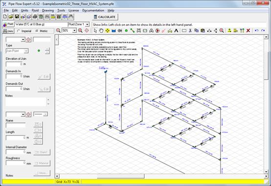
Piping Isometric Program

Flexible and Configurable Iso Creation M4 ISO can be used in automated or in manual mode, giving users more detailed influence over outputs. Its open data format provides a high degree of flexibility, allowing companies to configure their isometrics in line with corporate or project-specific requirements. Users can change their isometric drawings styles, as well as customise the system’s templates. Include 3D View of Pipe on Iso Drawing M4 ISO allows design engineers to include a 3D view of the relevant pipe segment with each isometric drawing, providing a welcome visual aid for fabricators and installers alike.
BOM and Parts Lists M4 ISO automatically generates configurable bills of material from the piping data generated by the 3D CAD or plant design system. BOMs can be placed directly onto an isometric drawing or exported to Excel, for example, for downstream use. Pipe Cut Lengths M4 ISO generates detailed cut-length lists, which are lists of individual cut pieces of pipe with end preparations, required for fabrication by the manufacturer. Pipe Spools M4 ISO also generates a list of spool pieces: sections of fully welded pipework delivered which are as a single piece.
AcornPipe is the best way of easily drawing isometric piping drawings. Save time and money by choosing AcornPipe today.
Piping Isometric Program
The system automatically recognises spool boundaries where components are not welded together, e.g. Flanged connections or valves. Notes on Pipework M4 ISO recognises any notes attached to the pipework in the 3D designs and positions them in the appropriate place on the 2D isometric drawing. Using Diagram Styles Users can choose between a variety of different styles prior to automatically generating their isometrics. Each style defines a different level of detail, including the amount of information displayed for fabrication, and whether or not a 3D view of the pipe segment is included. Templates M4 ISO uses standard templates on the basis of which the piping isometrics are generated. These templates can be customised in line with specific corporate requirements.
Configurable Diagram Styles M4 ISO allows administrators to configure their own isometric drawing styles according to company or project-specific requirements. The direction of the North angle, as well as the maximum number of components per drawing.
Simple Piping Isometric Drawing Program

Line styles, fonts, colours or the layer to be used can all be configured. Users can also customise the format and location of the bills of material, and cuts and spools lists.